Why Choose a Sheet Metal Die Cutting Machine?
Choosing a Sheet Metal Die Cutting Machine is not just a question of cutting speed. The right system must match the material, sheet thickness, part shape, production volume, and required edge quality. A press that handles thin aluminum well may not suit thicker stainless steel or a complex profile. Small details matter: die clearance, punch condition, sheet alignment, and lubrication can all affect burrs and dimensional consistency. That is where the real comparison begins.
A well-matched machine can produce repeatable parts, reduce manual handling, and support efficient production runs. For example, a shop making flat brackets may value quick changeovers, while a supplier producing thousands of identical panels may focus more on tooling life and cycle time. Faster is not always better. Feed accuracy, operator access, maintenance needs, and the availability of suitable dies also deserve attention. In practice, these trade-offs are easy to underestimate, especially when a machine looks capable on paper. Specifications help, but real samples and a clear review of production requirements offer better evidence. This guide will examine how die cutting works, where it performs well, and which machine features matter most. It will also consider costs and limitations, because no single setup suits every job. A thoughtful choice starts with the parts you actually make.
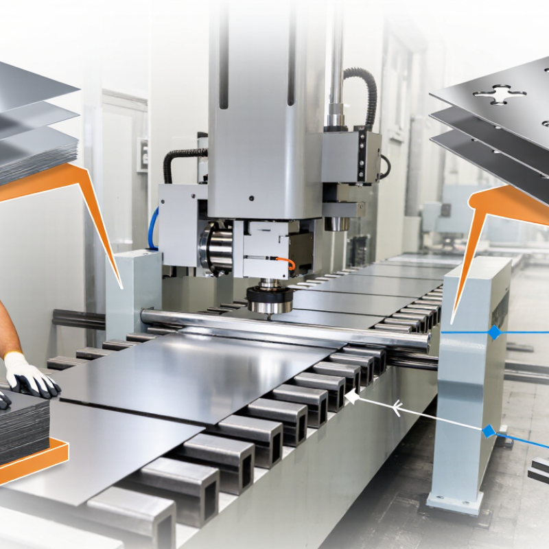
What a Sheet Metal Die Cutting Machine Does: Press, Punch, and Die
Why Choose a Sheet Metal Die Cutting Machine?
What a Sheet Metal Die Cutting Machine Does: Press, Punch, and Die
A sheet metal die cutting machine converts flat stock into repeatable shapes through pressure. The press drives a punch into the sheet, while a matching die supports and defines the cut. That is the cycle. On the shop floor, a sheet is positioned, clamped, and struck; the finished blank drops free or remains attached by small tabs. The exact setup depends on material thickness, part geometry, and required edge quality.
Punch and die clearance matters. Too little can increase tool wear; too much may leave a rough, tapered edge. Operators also check alignment, lubrication, and scrap removal before production. Small details matter. A burr on a bracket’s edge can complicate assembly, even when the outline looks accurate. I would not treat press speed alone as proof of good output: stable feeding and consistent tooling matter just as much.
The wider material context is substantial. The World Steel Association’s April 2024 Short Range Outlook projected global steel demand at 1,793 million tonnes for 2024. That forecast reflects steel use overall, not die-cutting demand, but it underscores why efficient sheet processing matters across manufacturing. For a buyer, the practical question is whether the press, punch, and die can repeatedly meet the part’s tolerances and volume. A test run with the actual sheet often reveals issues that a specification sheet cannot.
How Punch Force Depends on Cut Perimeter, Sheet Thickness, and Shear Strength
A sheet metal die cutting machine is useful when parts need consistent edges and repeatable dimensions. Its required punch force depends mainly on the cut perimeter, sheet thickness, and material shear strength. A longer outline means more metal is sheared at once. A thicker sheet also raises the load. Simple relationship, but not the whole story.
A first estimate is punch force ≈ cut perimeter × sheet thickness × shear strength. Keep units consistent: millimetres and newtons per square millimetre produce newtons. For example, a profile with many slots may demand more force than a compact shape with the same overall width. Corners and small features can also concentrate wear. Real cutting conditions matter.
Use the estimate to compare jobs and check whether the machine has suitable capacity. Then allow for material variation, die clearance, edge condition, and the machine’s working limits. Shear strength can vary between grades and batches, so a calculation is not a guarantee. A test cut may reveal burrs or deflection that the formula misses. I would leave room for uncertainty rather than plan around the exact minimum force.
Why Mild-Steel Die Clearance Often Starts at 5–10% of Thickness per Side
Why Choose a Sheet Metal Die Cutting Machine?
Why Mild-Steel Die Clearance Often Starts at 5–10% of Thickness per Side
Die clearance is the gap between the punch and die, measured on each side. For mild steel, tooling guidance commonly starts near 5–10% of sheet thickness per side. SME’s Tool and Manufacturing Engineers Handbook and ASM sheet-forming references discuss clearance as a key factor in sheared-edge quality and tool loading. It is a starting range, not a universal setting.
For 1.5 mm mild steel, that rule gives 0.075–0.15 mm clearance per side, or 0.15–0.30 mm total difference between punch and die dimensions. Too little clearance can increase force, heat, and edge rollover. Too much may leave a larger burr and a sloped cut face. Small difference. Big effect.
A die cutting machine helps maintain consistent punch alignment and repeatable strokes, but the material still sets the conditions. Steel strength, thickness variation, tool wear, and the desired edge finish can shift the useful setting. Check a fresh cut under magnification, then inspect burr height and fracture appearance. That practical check matters; handbook values cannot fully predict a worn tool or a coil with uneven thickness. Start within the range, record the result, and adjust carefully.
Which Metals, Sheet Gauges, and Part Shapes Suit Die Cutting?
Sheet-metal die cutting works well with mild steel, stainless steel, aluminum, copper, and brass, provided the tooling matches the alloy’s strength and ductility. Thin sheets cut cleanly. Yet “thin” has no universal limit: press capacity, punch clearance, sheet temper, and feature size all matter. Stainless steel can work-harden during cutting, while soft aluminum may distort around narrow slots. Not every alloy behaves alike. The International Aluminium Institute’s 2023 statistics report about 70.6 million tonnes of primary aluminum production worldwide; this signals broad material use, not a guaranteed die-cutting range.
Gauge suitability should be confirmed against the actual material thickness and tool design, rather than chosen from a generic chart. Very thin stock may buckle or develop burrs; thicker stock needs greater force and sturdy tooling. Simple flat shapes—discs, brackets, tabs, holes, and slots—are natural candidates. Tight inside corners and narrow webs need extra attention because they can weaken the tool or leave rough edges. Complex outlines can be produced with staged tooling, but setup cost may outweigh the benefit for small runs. A useful test is a sample blank. Then inspect its edges. The result is sometimes less neat than expected. Production reports describe material markets, not cutting performance, so a shop trial and measured edge quality remain essential.
How Production Volume, Setup Time, and Cycle Rate Guide Machine Choice
Choosing a sheet metal die cutting machine starts with the parts you actually need to make. A few hundred custom panels each month may not justify a high-speed production line. Thousands of identical brackets tell a different story. Estimate annual volume, but also check how often designs change. Frequent revisions can make flexible tooling more valuable than maximum output.
Setup time affects the real cost of each run. Changing a die, aligning the sheet, and checking the first parts all take time. If jobs are short, lengthy changeovers can erase the benefit of a fast cycle rate. For long runs, a steady machine that produces consistent parts may be the better fit. Ask suppliers for cycle-rate figures using your material thickness and part layout, not just ideal test conditions. Then compare them with usable output, including loading, inspection, and routine tool maintenance. Small delays add up. A spreadsheet helps, but its assumptions deserve a second look: scrap rates and operator availability are easy to underestimate. The best choice balances volume, setup effort, and dependable cycles for your actual production mix.
Why Choose a Sheet Metal Die Cutting Machine?
How production volume, setup time, and cycle rate guide machine choice
How to read this: The chart compares estimated total hours for three batch sizes, separating setup time from run time. In this example, die cutting has a 2-hour setup and a 600-parts-per-hour cycle rate; laser cutting has a 0.25-hour setup and a 60-parts-per-hour cycle rate.
This is a calculated planning example, not an industry benchmark. Under these assumptions, die cutting takes longer for small batches because of setup, but its faster cycle rate makes it more time-efficient at higher volumes. Actual results depend on the part, material, tooling, and production conditions.